Saturn V Major Components


S-IC / S-II Interstage
The interstage was a cylindrical structure mounted between the S-IC and S-II stages.
Eight solid fueled ullage motors, located around the perimeter of the interstage, fired after first stage separation. Thrust from the ullage motors forced propellants to settle in their tanks, ensuring pressure in the propellant feed lines. The motors fired for approximately four seconds.
Early flights included eight ullage motors. The number was reduced on later missions.
Around thirty seconds after first stage separation, explosive charges would be fired, separating the interstage section from the second stage.
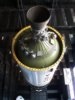
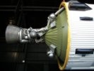
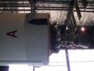
Photo of an S-IC / S-II Interstage
What appears to be a Saturn V Interstage being used as a building at the United States Space and Rocket Center. (Photos: Richard Kruse, 2008)


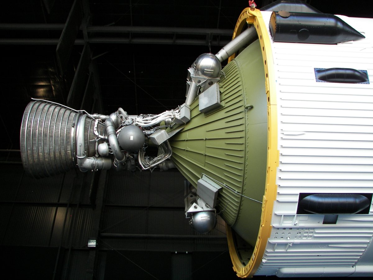
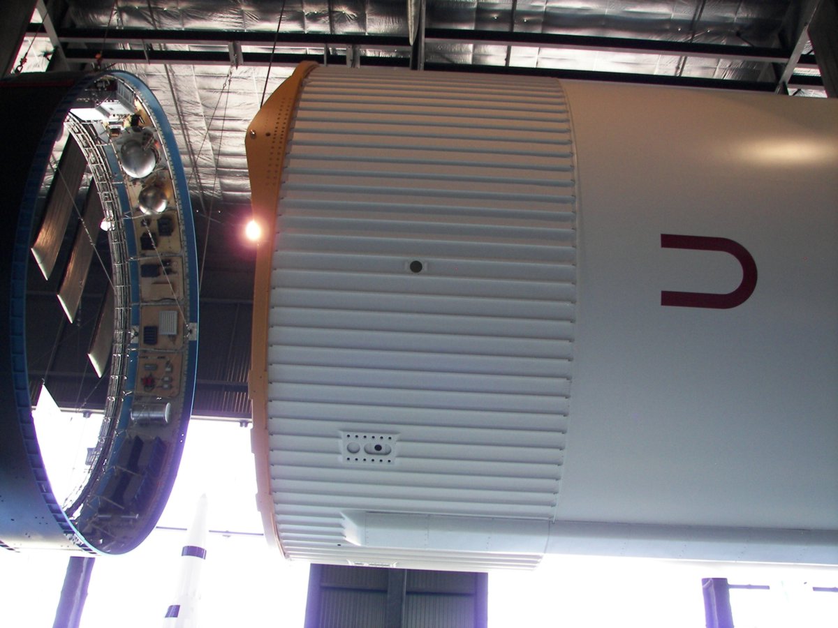
S-IVB aft Interstage
Shaped like a truncated cone, the S-IVB aft interstage connected the S-II stage with the S-IVB stage.
The interstage included four retrorockets. The forward firing, solid fueled rockets helped ensure a clean separation between the S-IVB and the S-II.
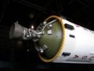
Photo of S-IVB aft Interstage
What appears to be an S-IVB aft Interstage being used as a building at the United States Space and Rocket Center. (Photos: Richard Kruse, 2008)


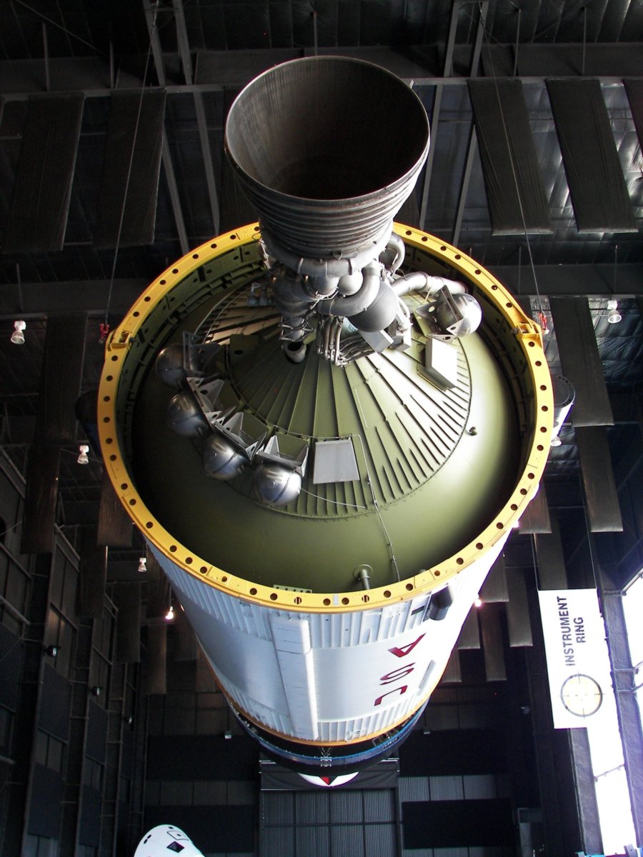
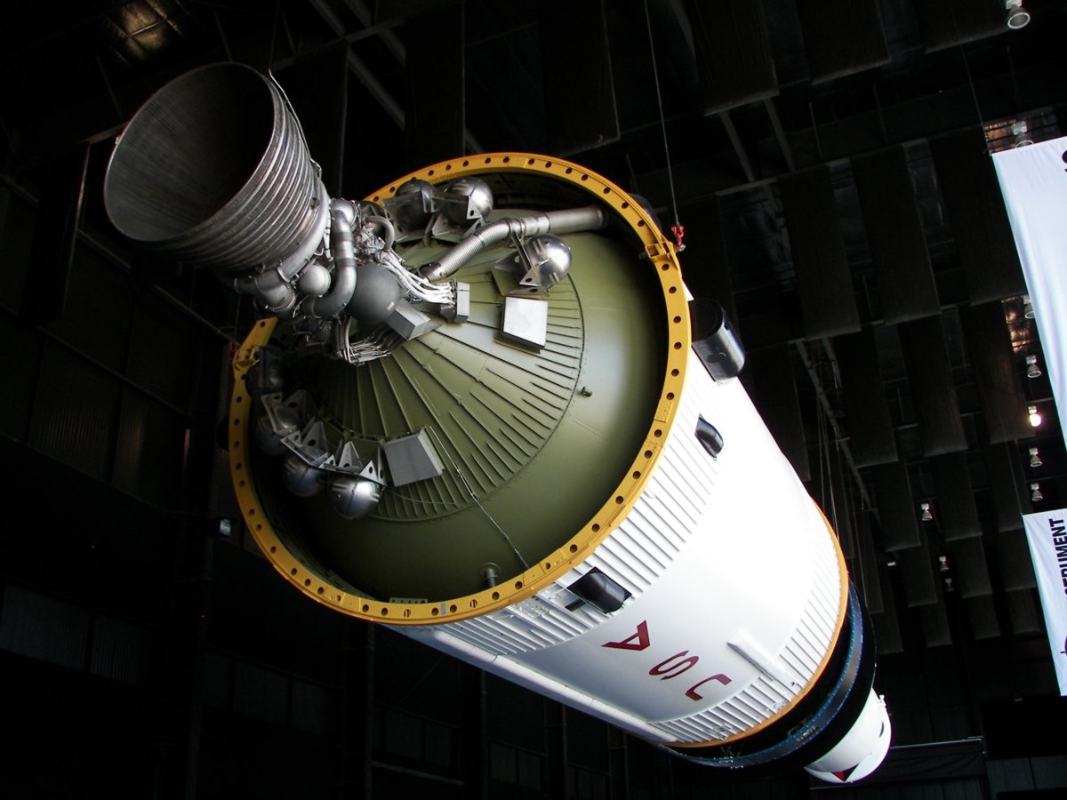
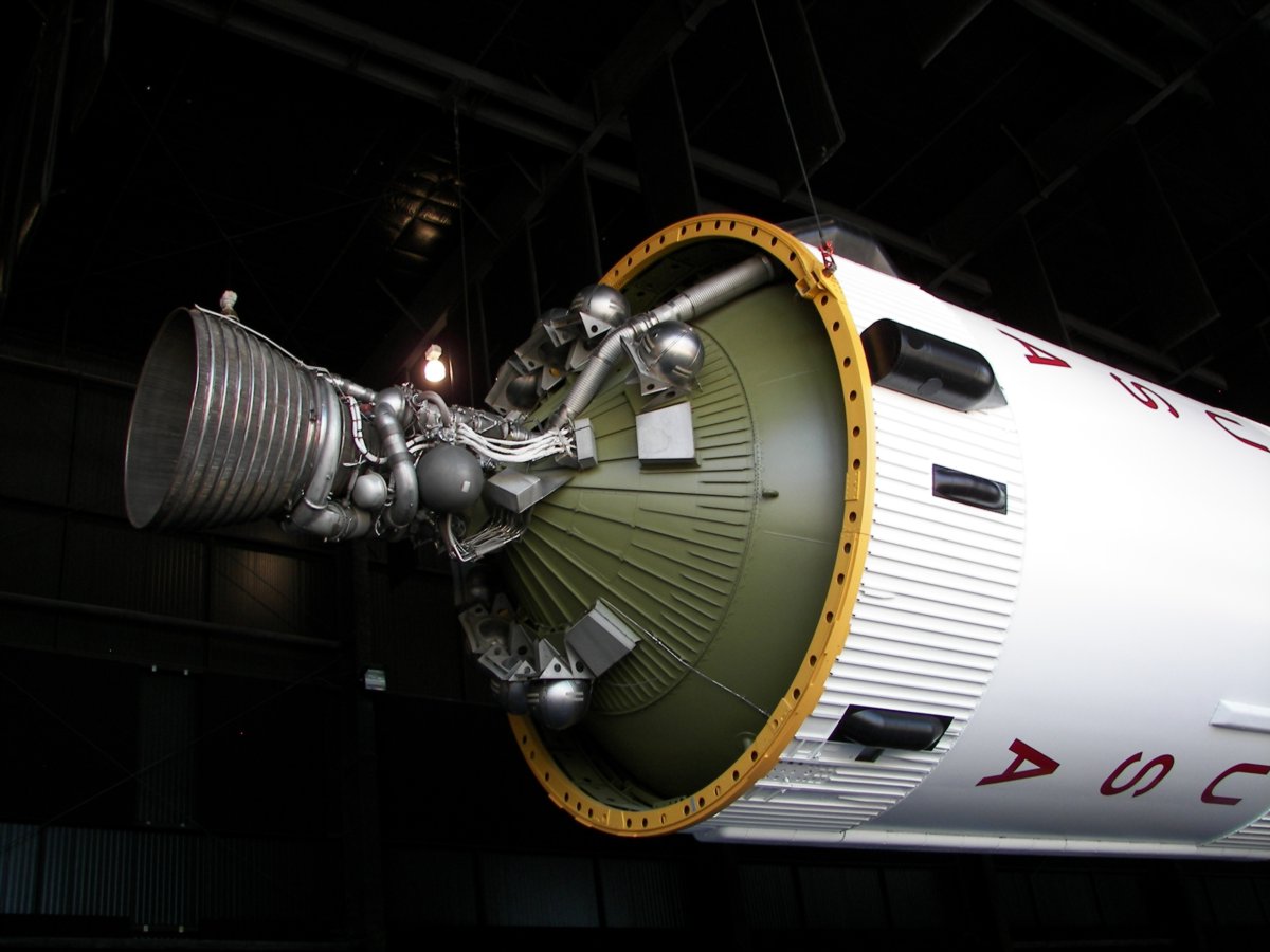
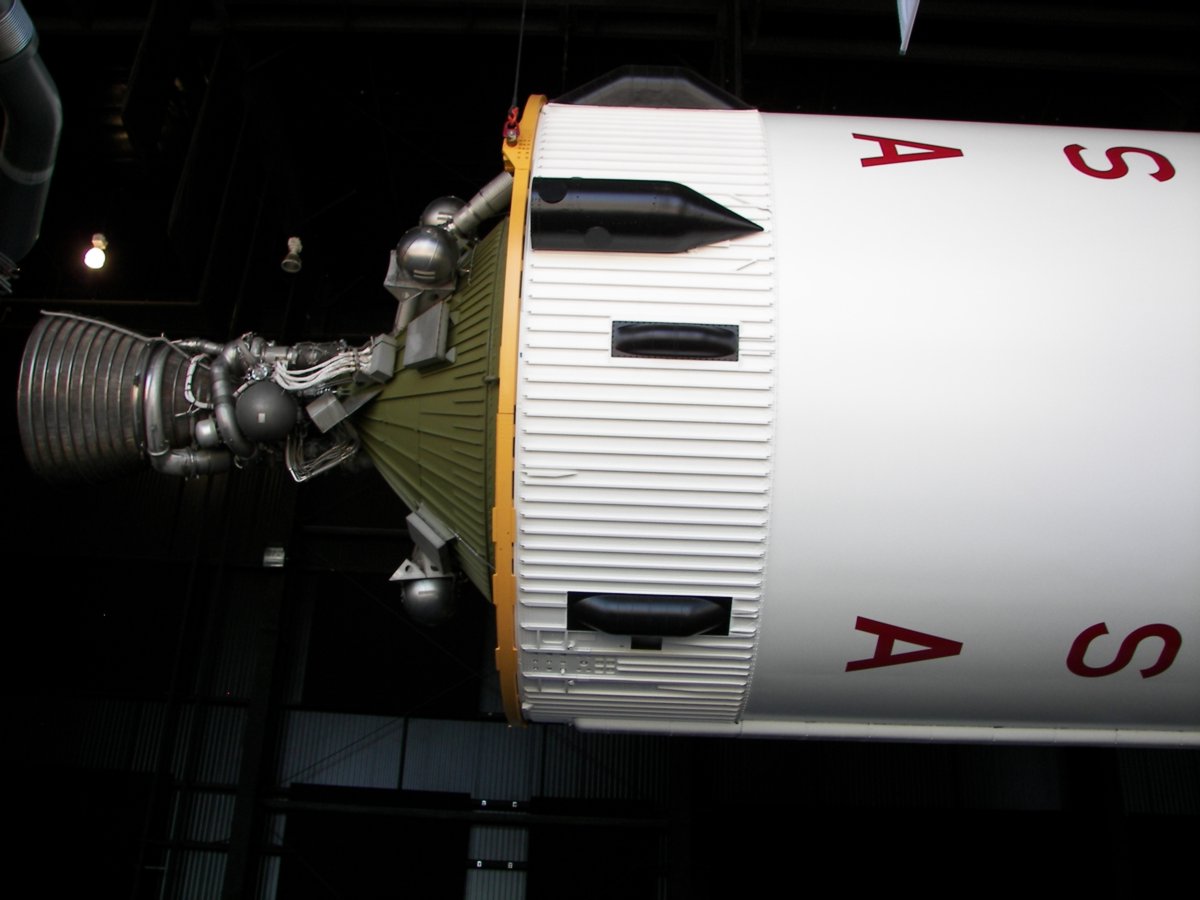
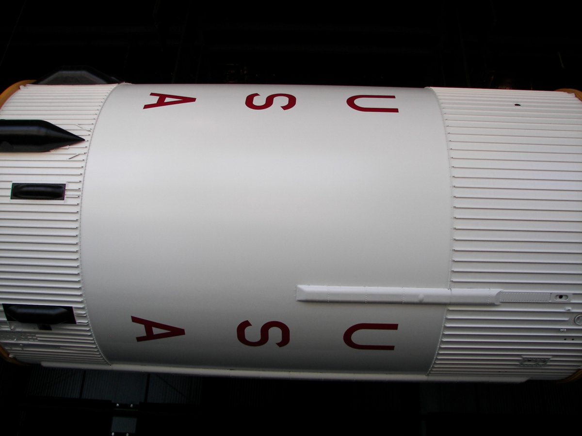
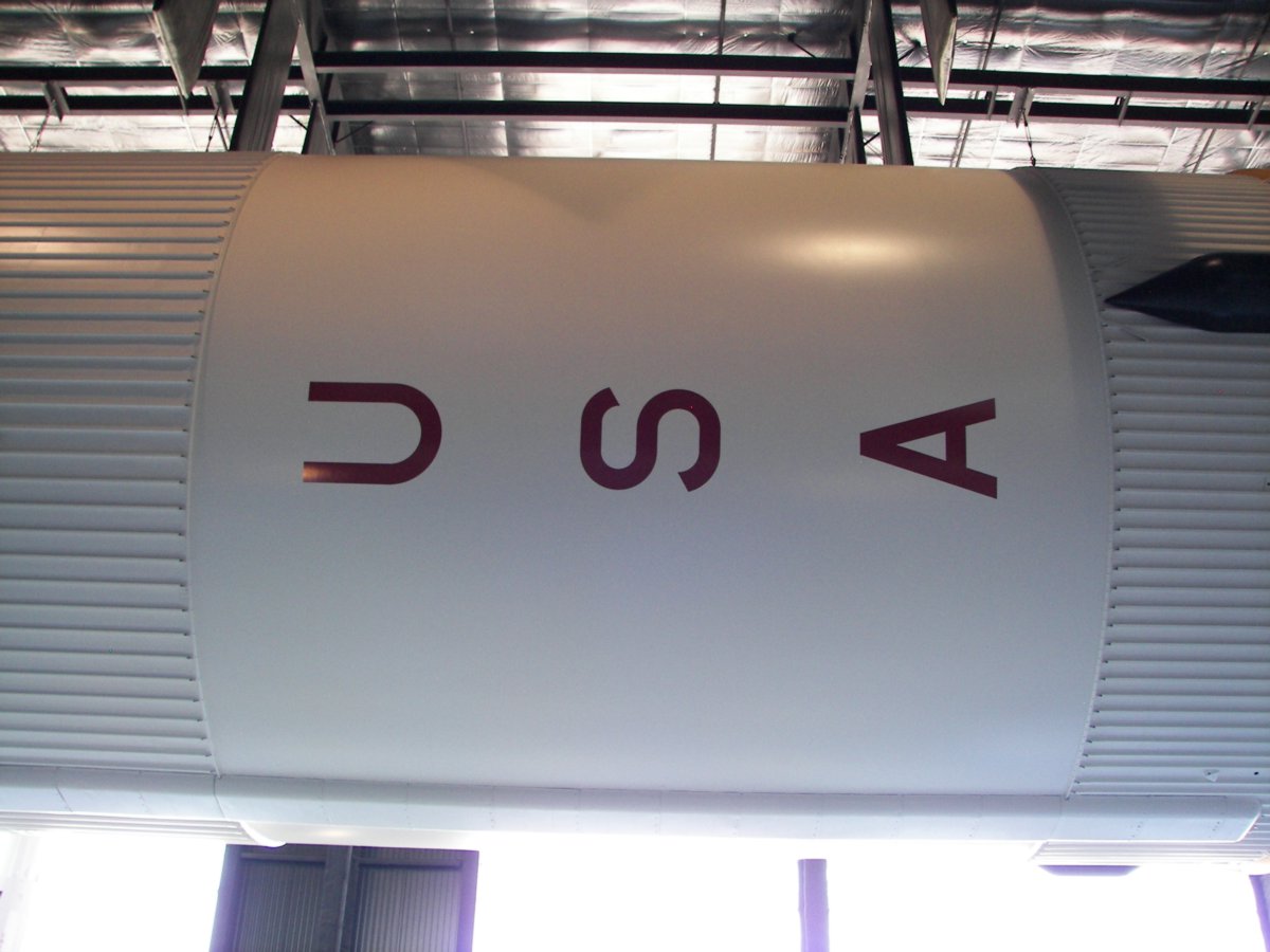
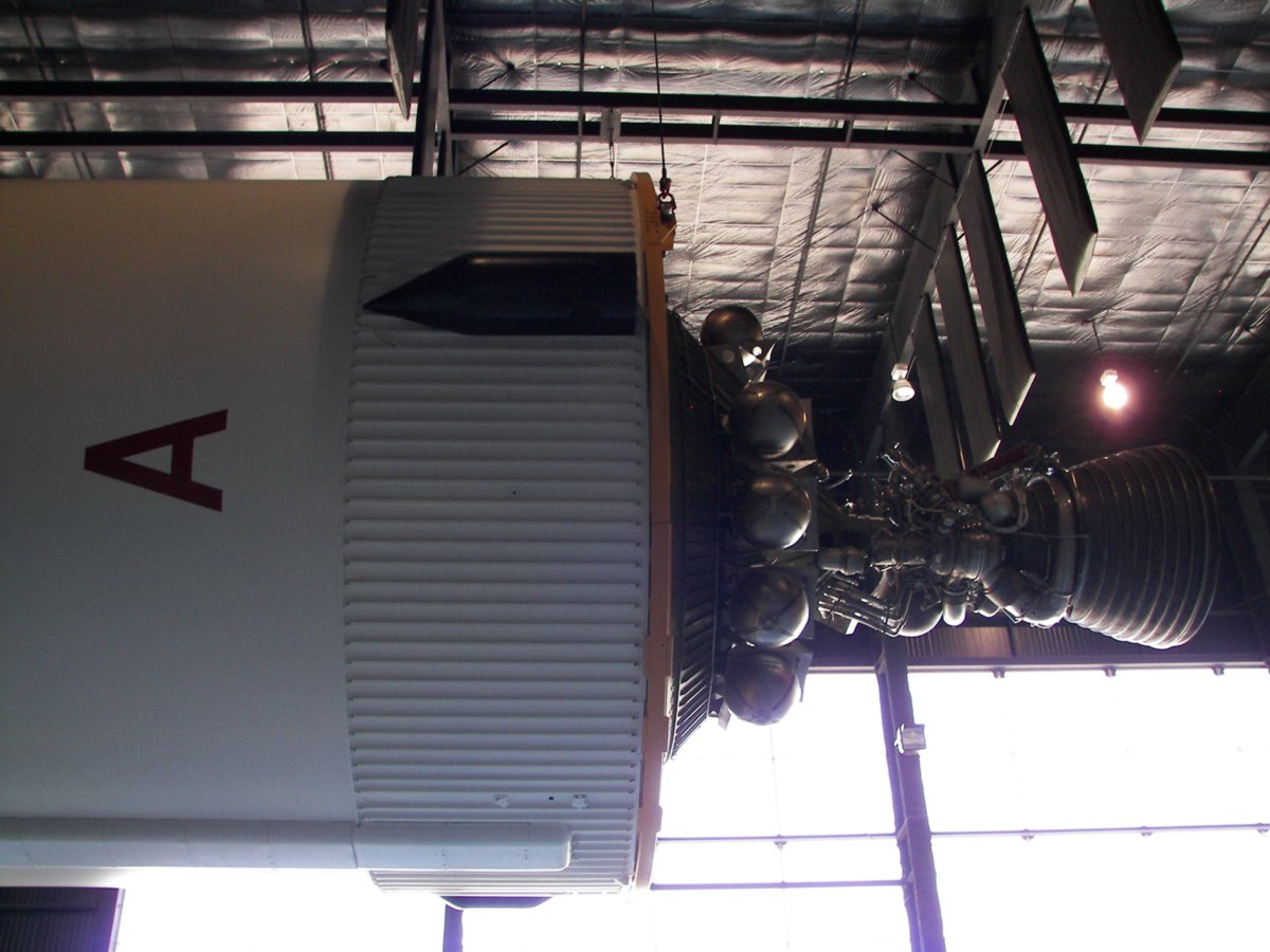
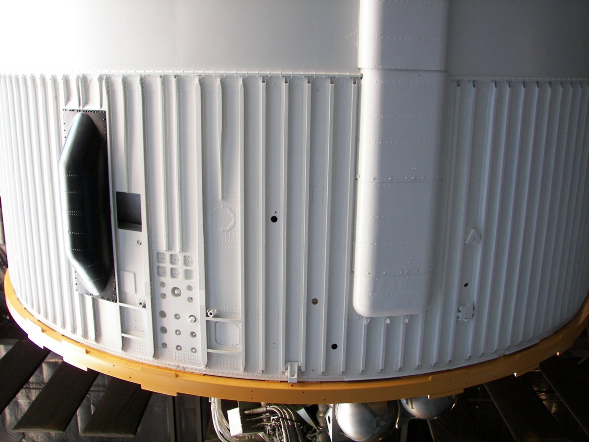
S-IVB Stage
Developed by McDonnell Douglas, the S-IVB served as third stage for Saturn V rockets. Fueled with liquid hydrogen and liquid oxygen, the S-IVB was powered by a single, restartable, J-2 engine.
A single propellant tank was divided into two compartments by a common bulkhead. The upper compartment would contain liquid hydrogen, while the lower compartment was for liquid oxygen.
Two solid propellant rocket motors, mounted to the aft skirt, were fired during separation of the second and third stages. Thrust from the motors helped to settle fuel and oxidizer in the main propellant tanks, insuring a safe start for the J-2 engine.
On Lunar flights, the S-IVB stage would conduct two burns. First, to put the stage and Apollo spacecraft into a parking orbit. After a period of system checks, the S-IVB would be started a second time. Called a trans-lunar insertion burn, this firing sent the stack on its way to the Moon.
Auxiliary Propulsion System (APS)
The APS provided attitude control and ullage control for the third stage. The system included two pods, mounted 180 degrees apart on the aft skirt assembly. Each pod included three attitude control engines and a single ullage engine. Each pod included tanks for fuel, oxidizer, and high pressure helium.
The attitude control engines provide pitch, roll, and yaw control for the stage. The ullage engines would fire after the first J-2 engine burn to minimize unwanted propellant movement within the tanks. Later, the ullage engines would be used to settle the fuel and oxidizer prior to restarting the main engine.
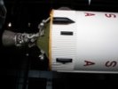
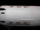
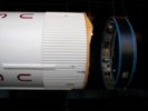
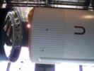
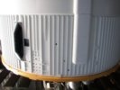
S-IVB Stage Photos
Saturn S-IVB Stage on display at the United States Space and Rocket Center. (Photos: Richard Kruse, 2008)

Saturn 5 S-IVB stage on display at the Kennedy Space Center. (Photos: Kevin Reynolds, 2000)


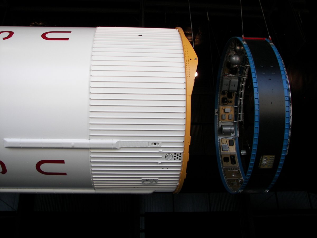
Saturn Instrument Unit
Designed by NASA and built by IBM, the instrument unit (IU) was located between the S-IVB third stage and the SLA
Electronics and electrical equipment located within the IU provided guidance, tracking, and communication services for the rocket. Critical components were mounted on cold plates for cooling. An Environmental Control System (ECS) circulated liquid coolant through the cold plates.
On the ground, IU power was supplied by external sources via an umbilical connection. Shortly before launch, power would switch to internal batteries. Four 28v, 350 amp-hour, batteries were included.
The IU structure became a load bearing part of the rocket and supported the weight of the Apollo spacecraft above.
Instrument Unit Photos
Saturn V Instrument Unit on display at the United States Space and Rocket Center. (Photos: Richard Kruse, 2008)


Saturn V Instrument Unit on display at the Udvar-Hazy Center. (Photos: Richard Kruse, 2009)


Spacecraft Lunar Module Adaptor (SLA)
The spacecraft lunar module adaptor, or SLA, was a tapered section connecting the Instrument Unit with the base of the Apollo service module. The SLA enclosed and protected the lunar module during launch.
Saturn SLA Photos
Saturn V SLA on display at the Kennedy Space Center. (Photos: Kevin Reynolds, 2000)


Boost Protective Cover and Launch Escape System
Located at the very top of the stack, the launch escape system, or LES, contained a solid rocket motor designed to pull the command module away from the rocket in event of a series emergency on the pad or during early phases of the launch.
A boost protective cover, or BPC, protected the Apollo command module during launch.
A smaller rocket motor is used to pull the LES and BPC away from the command module during normal flights. This occurs shortly after second stage ignition.
Apollo Launch Escape System (LES) and Boost protective Cover (BPC)Photos
Apollo BPC and LES on display at the United States Space and Rocket Center. (Photos: Richard Kruse, 2008)